
Skip to content

DryLine® Modular channel drain configurator

The DryLine® Modular configurator helps you quickly and conveniently design a channel drainage system to your project. The 3D view lets you immediately visualize the system as it takes shape and allows you to customize the chnnael drain to fit your site. The configurator assists and guides you in selecting the right modules and other components for your system. This allows you to design a fully functional channel drain system in one go. Guessing and manual work are reduced when all the necessary modules and components are available in a single view.

Once the configuration is complete, you can export it directly into your HVAC plan, for example, as a .dxf file, or share the configuration with others, or request a quote for it.
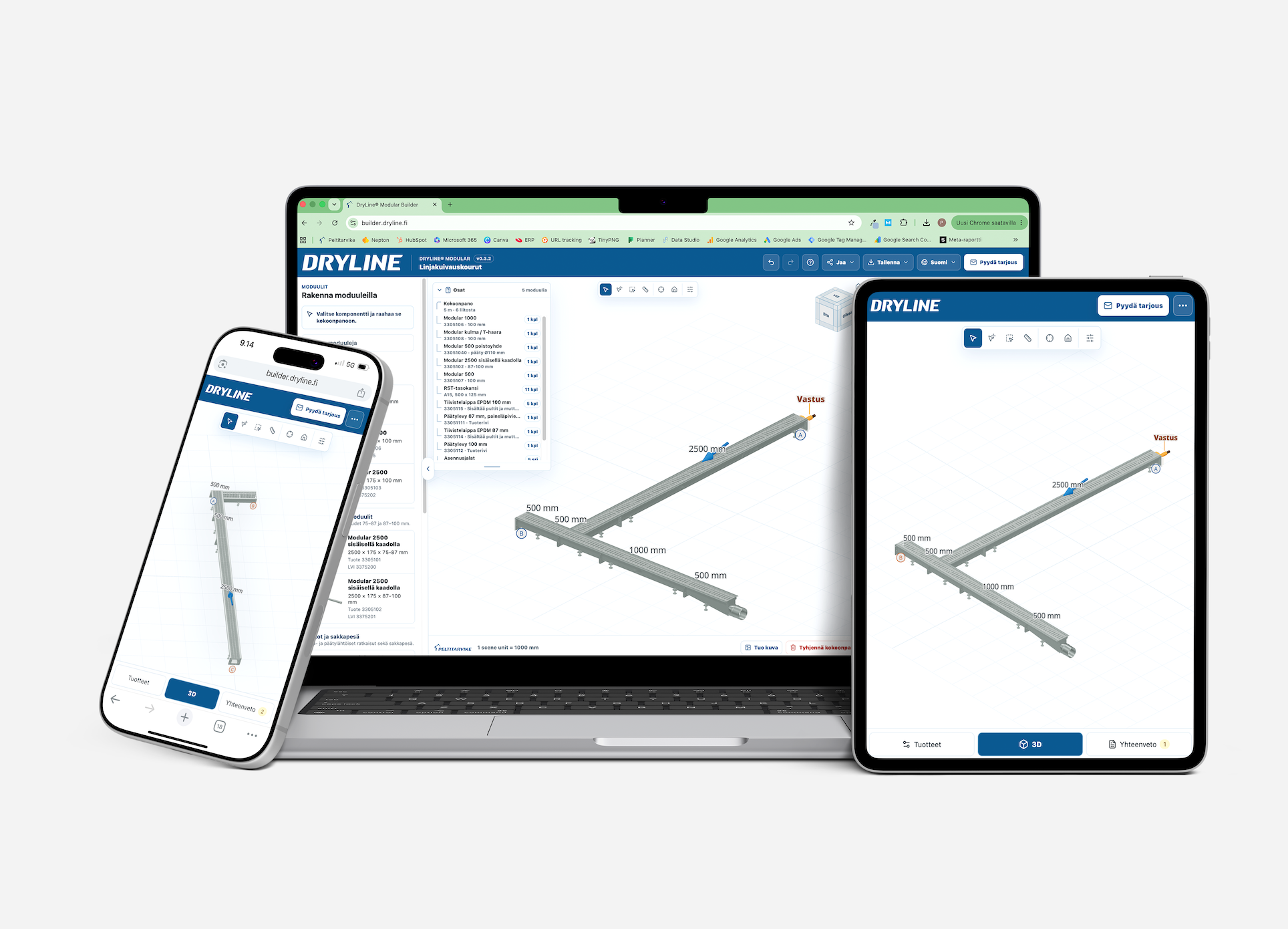
DryLine channel drain configurator

Here’s how to design a channel drainage system using the configurator

  1. Go to www.builder.dryline.fi.
  2. Specify the basic information for the configuration: application, load class, grating, and required accessories. A heating element keeps the channel drain ice-free year-round, and NBR rubber is selected as the seal flange for the modules when designing the system for a site where gasoline may leak into the channel drain or where it is exposed to other chemical stresses.
  3. Start planning the system.
  4. Select or drag the suitable channel drain modules from the left sidebar of the configurator into the assembly view. The configurator will guide you to the position where the selected module can be joined.
  5. View the configuration from different angles. You can see a real-time parts list for the configuration in the upper-left corner of the view. Click the Home button to return to the default view at any time.
  6. By clicking on a module added to the configuration, you can — depending on the module — for example, change the direction of the internal slope and the angle of the corner module, or remove the module from the configuration.
  7. You can import an image or a drawing into the assembly view, design a channel drain system on top of this document, and customize the assembly to meet the needs.
  8. Once the configuration is complete, remember to specify an outlet module or end plate for the open ends of the lines using the right-hand sidebar of the configurator. If you have selected a heating element as an accessory for the channel drain, at least one end of the line must be equipped with an end plate that has a pressure grommet.
  9. If necessary, edit the basic information you entered earlier in the right sidebar.
  10. Send the design you've created to your email for later editing, or download the finished design directly in the file format of your choice, such as .dxf, and import the file into your AutoCAD project. You can also share the configurator's assembly view with others.
  11. You can also request a quote for the assembly of a channel drainage system you have designed. The configurator will guide you in correcting any errors in the assembly before you submit your quote request. Fill out your contact information and project details on the quote request form. Our sales representatives will review all the components included in your assembly and respond to your quote request as soon as possible. 

The configurator is developed by Lemigo Oy.

lemigo_bg_removed